µSDX 極座標変調、ポーラー変調(SSB 第4の方式)に関する資料 [SDR]
昨年、ハードディスクのトラブルで µSDX のいろいろな資料を失くしてしまったので、こちらに参照先を残しておきます。
1.QEX March/April 2017, Brian Machesney, K1LI and Tony Brock-Fisher, K1KP の The Polar Explorer の記事
彼らは PA の高効率化を目指して検討したようです。冒頭の一部を抜粋すると、
「100 Wトランシーバーのこの由緒あるサイドキックを交換するために単に数千ドルを費やすのではなく、ポーラー変調と呼ばれる手法を使用して、法定制限のハム送信機のサイズ、重量、およびコストを削減することの実現可能性を探ることにしました 、「PolarExplorer」。です」
とあります。
MBF.pdf (arrl.org)
2.Application of the polar-loop technique to HF SSB transmitters. — the University of Bath's research portal
1983 年の資料ですが、ゼロクロスするところの処理に関して説明があります。
キモはここかと。
極座標変調をアナログ回路で実現しているので、周波数を可変するのは VCO で実現しています。その説明にゼロクロスの処理があります。
(ざっと眺めただけなので、内容を正しく理解しているか不安ではあります。ディジタル信号処理による実現では異なるかもしれません)
一部を抜粋すると
Page 78
3.4.2 180° phase transitions of the phase modulated carrier at the zero crossings of the RF signal
Whenever the envelope of an SSB signal falls to zero there is an instantaneous 180° phase transition of the phase modulated carrier which must be reproduced by the VCO under the control of the phase loop.
~ 途中省略 ~
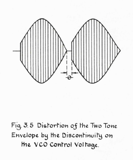
The amplitude of the spurious components caused by the distortion of the two tone signal has been determined by considering a discontinuous low frequency sinusoid which is multiplied by a carrier wave to produce the waveform of figure 3.5 (see appendix B).
Page 293
APPENDIX B
SPURIOUS EMISSION CAUSED RY TUE LOSS OF FREQUENCY LOCK AT THE ZERO CROSSINGS OF MODULATED OF RF SIGNAL
This appendix covers the derivation of equations 3.4-3.7 introduced in section 3.4.2 to determine the distortion produced by a Polar-Loop Transmitter at the zero crossings of a two tone signal.
~ 以下省略 ~
Page 353
A photograph of the two tone output waveform of the transmitter at 1 kW PEP together with the gate control voltage and VCO control line voltage is shown in figure H.6, no compensating time delay was used when this photograph was taken and therefore discontinuities may be seen on the VCO control voltage. A gate control voltage variation of only 100 mV peak to peak was required to correct for any amplitude distortion. This correcting signal perturbates around a mean DC level of about 3 volts (controlled By the amplitude loop), the mean level determining the gain of the VMOS amplifier.
Page 356
Fig. H.6
Top: Gate Modulating Voltage
Middle: Two Tone Output Waveform
Bottom: VCO Control Voltage

Application of the polar-loop technique to HF SSB transmitters. — the University of Bath's research portal
3.L.R.Kahn, Single sideband transmission by envlope elimination and restoration,
これは極座標変調の出発点となった 1952 年の論文です。
IRE(IEEEの前身)に投稿されています。
この論文は最新の論文でも引用されたりしているものです。
こちらは IEEE のメンバーであれば検索して見ることができます。
今までブログに書いたポーラー変調のリンク先
µSDX で使われている「ポーラー変調方式」
µSDX で使われている「ポーラー変調方式」(その2)(説明を変更)
1.QEX March/April 2017, Brian Machesney, K1LI and Tony Brock-Fisher, K1KP の The Polar Explorer の記事
彼らは PA の高効率化を目指して検討したようです。冒頭の一部を抜粋すると、
「100 Wトランシーバーのこの由緒あるサイドキックを交換するために単に数千ドルを費やすのではなく、ポーラー変調と呼ばれる手法を使用して、法定制限のハム送信機のサイズ、重量、およびコストを削減することの実現可能性を探ることにしました 、「PolarExplorer」。です」
とあります。
MBF.pdf (arrl.org)
2.Application of the polar-loop technique to HF SSB transmitters. — the University of Bath's research portal
1983 年の資料ですが、ゼロクロスするところの処理に関して説明があります。
キモはここかと。
極座標変調をアナログ回路で実現しているので、周波数を可変するのは VCO で実現しています。その説明にゼロクロスの処理があります。
(ざっと眺めただけなので、内容を正しく理解しているか不安ではあります。ディジタル信号処理による実現では異なるかもしれません)
一部を抜粋すると
Page 78
3.4.2 180° phase transitions of the phase modulated carrier at the zero crossings of the RF signal
Whenever the envelope of an SSB signal falls to zero there is an instantaneous 180° phase transition of the phase modulated carrier which must be reproduced by the VCO under the control of the phase loop.
~ 途中省略 ~
The amplitude of the spurious components caused by the distortion of the two tone signal has been determined by considering a discontinuous low frequency sinusoid which is multiplied by a carrier wave to produce the waveform of figure 3.5 (see appendix B).
Page 293
APPENDIX B
SPURIOUS EMISSION CAUSED RY TUE LOSS OF FREQUENCY LOCK AT THE ZERO CROSSINGS OF MODULATED OF RF SIGNAL
This appendix covers the derivation of equations 3.4-3.7 introduced in section 3.4.2 to determine the distortion produced by a Polar-Loop Transmitter at the zero crossings of a two tone signal.
~ 以下省略 ~
Page 353
A photograph of the two tone output waveform of the transmitter at 1 kW PEP together with the gate control voltage and VCO control line voltage is shown in figure H.6, no compensating time delay was used when this photograph was taken and therefore discontinuities may be seen on the VCO control voltage. A gate control voltage variation of only 100 mV peak to peak was required to correct for any amplitude distortion. This correcting signal perturbates around a mean DC level of about 3 volts (controlled By the amplitude loop), the mean level determining the gain of the VMOS amplifier.
Page 356
Fig. H.6
Top: Gate Modulating Voltage
Middle: Two Tone Output Waveform
Bottom: VCO Control Voltage
Application of the polar-loop technique to HF SSB transmitters. — the University of Bath's research portal
3.L.R.Kahn, Single sideband transmission by envlope elimination and restoration,
これは極座標変調の出発点となった 1952 年の論文です。
IRE(IEEEの前身)に投稿されています。
この論文は最新の論文でも引用されたりしているものです。
こちらは IEEE のメンバーであれば検索して見ることができます。
今までブログに書いたポーラー変調のリンク先
µSDX で使われている「ポーラー変調方式」
µSDX で使われている「ポーラー変調方式」(その2)(説明を変更)


コメント 0